Garmin 6 Pin Wiring Diagram
Hardwire with part 33-561-01 for depth only B260 SS270W SS264. Wiring Diagrams for Conventional non-CHIRP Transducers.
 Db9 Wiring Diagram Esquemas Eletronicos Cat5 Engenharia Eletronica
Garmin 740s wiring diagram utility trailer wiring diagram new 7 pin trailer plug wiring diagram rh originalstylophone.

Garmin 6 pin wiring diagram. Wiring Diagrams for Conventional non-CHIRP Transducers. Lowrance Blue 7-Pin Connector. In my brief look at the wiring diagrams Furuno is only using 5 pins but you show as connecting at least 6 or 7 wires together.
Refer to the wiring diagram on pages 3-4 which applies to your GPS units type of interface connector. Do not cut a Garmin differential 8-pin transducer. Required connector and associated hardware are supplied with the Mounting Rack Backplate and Connector kit Garmin PN 010-10161-01.
In my brief look at the wiring diagrams Furuno is only using 5 pins but. RJ45 wiring pinout for crossover and straight through LAN Ethernet network cables. 6-pin Transducer to 8-pin Sounder Adapter Wire Block PART NUMBER.
Wiring Diagrams non CHIRP Transducers. The camera wire is foldedBC 30 Wireless Backup Camera 2ZQHUV 0DQXDO Introduction WARNING See the Important Safety and Product Information guide in the product box for product warnings and other important information. Note that this item comes from the Usa and may take 7-10 days to deliver if not in stock.
Solder the powerdata cable Data Out to the Receive Data RxD pin 2 of the DB9 DB25 pin 3 Information for wiring a Garmin GPS to a DIN-8 connector is provided as a courtesy to. These wires are used to sharing user data between the STRIKER and the ECHOMAP 2 series devices. These diagrams are for the use of professional installers.
Pinout of Garmin GPSMAP power and data cableUsed by GPSMAP 276C GPSMAP 278 GPSMAP 296 GPSMAP 376C GPSMAP 378 GPSMAP 396 GPSMAP 478 GPSMAP 495 GPSMAP 496. Airmar Wiring Diagram Garmin 6 pin D Airmar Transducer Mix and Match Airmar CHIRP Transducer. GARMIN GPS to PC Wiring Instructions Introduction Refer to the wiring diagram on pages which applies to your GPS units type of interface connector.
Use Garmin cable 010-11612-00 Garmin 8-Pin. 7 Trim the drain wire à to approximately 14 mm 916. 5 Using a sharp knife insert the blade between the cable shield and jacket and slit the jacket 16 mm 5 8 in from the cut end of the cable.
Does anyone have. 010-11613-00 6999 USD. Marine Electronics Forum - Need Help Splicing Transducer Wires - Garmin to 10 pin pigtail correctly to my existing Airmar B60 with Garmin 8 pin plug.
Not possible - Impedance too low. The Garmin Marine Network requires cross-over cables not exceeding 100 m between devices. 6-pin connector Depth only.
Just enter the first few numbers of the part number and see the results immediately. 6 Peel the jacket back and remove the slit portion. This adapter allows you to connect the wires on legacy 6-pin transducers with newer sonar that require a 8-pin connection.
Garmin units with 6-pin. Wiring Diagram Pics Detail. Enter any of the following into the search box.
Speed sensor with Y-cable for Garmin 6-Pin connector -6G. What is the pinwire color assignment to splice on the Furuno 10 pin a wiring schematic for the Garmin Airmar B 6 pin transducer is. Airmars transducer cross reference offers a variety of transducer informationfrom wiring diagrams to sounder compatibility and more.
The GSD 24 adapter is not meant for use with a Garmin differential 8-pin transducer. Appropriate wire connectors for the assembly as opposed to soldering the connections. To the wire block in the 12-pin adapter as shown in the wiring block table.
Use this adapter to connect a non-differential transducer such as a legacy GarminAirmar 6-pin transducer to a. Speed sensor with Y-cable for Garmin 6-Pin connector -6G. Red and Black - The Red wire connects to the positive battery terminal.
See figures B4 and B5 on pages 43 and 45 for interconnect wiring diagrams. Instead plug it directly into the GSD 24 according to the GSD 24 Installation Instructions. Pinout diagrams and wire colours for Cat 5e Cat 6 and Cat 7.
The Black wire connects to the negative battery terminal or ground. Check to see if an adapter cable exists see the Adapters page. Airmar Wiring Diagram Garmin 1kw 8 pin DT Airmar Transducer Mix and Match Airmar CHIRP Transducer.
Not possible - Temperature not compatible B164 B258 TM258. Protect your most precious cargo. Garmin -6G Adapter Cables.
You can consult the wire color tables to identify the wire functions for some Garmin and Airmar transducers. Before attempting to rewire a transducer connector you should. Garmin Wireless Backup Camera Installation 10 The fuse box is the only thing exposed on the inside of the boot.
Wire Block Number Wire Function 1 ShieldGround 2 Temp 3 GID 4 XID 5 Right - Low depth - 6 Right Low depth 7 Down - Hi depth - 8 Down. Blue and Brown optional - The Blue wire is the Tx Transmit and the Brown is the Rx Receive wire. Solder the powerdata cable Data Out to the Receive Data RxD pin 2 of the DB9 DB25 pin 3 4.
Adapter Cables for Transducers with Garmin 6-Pin connectors Garmin and Navman both use the CX connector but the transducer wiring is not the same.
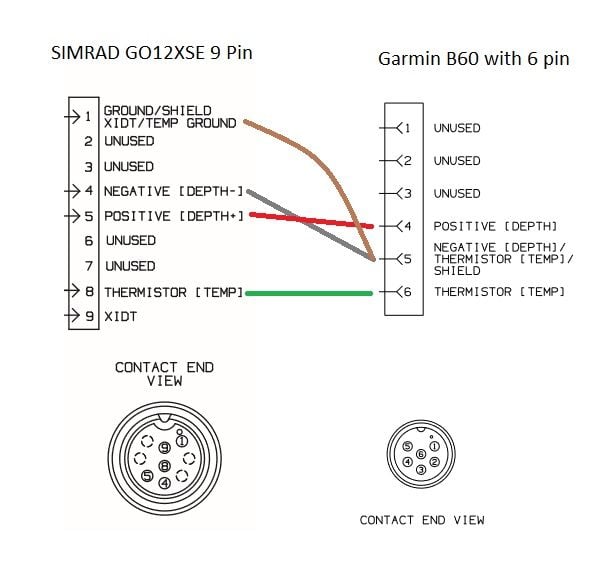 Hardwire Garmin B60 6pin To Simrad 9pin Wiring Help The Hull Truth Boating And Fishing Forum
 Garmin Interface Garmin Gps Garmin Gps
 Airmar Wiring Diagram Garmin B164 8 Pin D T Best Deal Blue Bottle Marine
 Unique Electrical Wiring Diagram Sample Free Diagram Wiringdiagram Diagramming Diagramm Visuals Visualisation Gra Car Stereo Car Stereo Speakers Diagram
 Pin On Wiring


