Garmin Gps 17 Wiring Diagram
Variety of garmin wiring diagram. Schema de Garmin 17 Gps Wiring Diagram.
 Installing An Nmea 0183 Gps Antenna Hvs To A Garmin Chartplotter Garmin Support
Bmw 328i Fuse Box Passenger It is far more helpful as a reference guide if anyone wants to know about the homes electrical system.

Garmin gps 17 wiring diagram. If two or more GPSMAP 2006C2010C units are installed only one GPS 17 needs to be installed. Garmin Gpsmap 695 696 Power Data Cable Pinout Diagram. Need Wiring Diagram For Pioneer Deh1400.
Thread the cable though the pole mount. If two GPSMAP 21062110 units are installed and connected only one GPS 17 antenna needs to be installed. For Macintosh users Garmin does not support Macintosh at this time and does not have Macintosh software or connectors available.
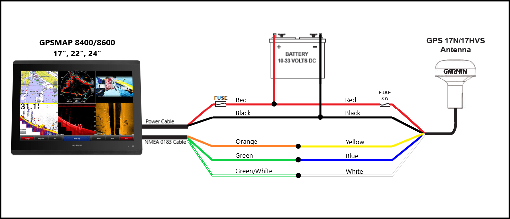
The wiring diagrams and accompanying notes in this manual should be followedG3X is designed for non-certified installation in LSA and experimental aircraft combining MFD and PFD reference with electronic engine gauges built-in GPS digital ADAHRS and detailed moving map with obstacleterrain databases and much more. PowerData Cable Wiring The following pages contain several wiring diagrams. WIRE COLOR GPS 17N17HVS Antenna BLACK GROUND.
It shows the parts of the circuit as streamlined forms and also the power as well as signal connections between the gadgets. Port 2 is used for RTCM input only. To ensure the best reception mount the GPS 17 in a location that has a clear unobstructed view of the sky.
Is the least efficient diagram among the electrical wiring diagram. A wiring diagram is a simplified standard photographic representation of an electric circuit. Wiring 3 Switches In One Box Diagram It is far more helpful as a reference guide if anyone wants to know about the homes electrical system.
Its components are shown by the pictorial to be easily identifiable. Use 22 AWG 18 AWG for the Red and Black wires shielded twisted-pair wiring for extended runs of wire. Garmin Gps Antenna Wiring Diagram Duraflame Electric Log Heater Wireing Duramax Yenpancane Jeanjaures37 Fr.
The GPS 17 connects to the 18-pin PowerData cable on the GPSMAP 3006C3010C and provides the GPSWAAS signal for the unit. Garmin Support Center is where you will find answers to frequently asked questions and resources to help with all of your Garmin products. Olathe KS 66062 USA.
4 GPS 17 Installation Guide MOUNTING THE GPS 17 To attach the enclosed pole to the base. Solder all connections and seal the connection with heat shrink tubing. Information for wiring a Garmin GPS to a DIN-8 connector is provided as a courtesy to Macintosh users.
The GPS 17HVS produces RS-232 data in the industry-standard NMEA 0183 format so it interfaces easily with laptops or chartplotters. The GPS 17 connects to the 18-pin PowerData Cable on the GPSMAP 2006C2010C and provides the GPSWAAS signal for the unit. Its components are shown by the pictorial to be easily identifiable.
Wiring Diagram Garmin 17 Gps Wiring Diagram 9 out of 10 based on 10 ratings. The orange accessory on wire is used when wiring the GPS 17x to a Garmin chartplotter or other NMEA 0183 device that has a defined accessory signal wire. Is the least efficient diagram among the electrical wiring diagram.
190-00885-07 Revision B. GPS 17x HVS. Align the tab on the pole to the notch on the base.
Page 8 TO SELECT BETWEEN VISUAL AND AUDIBLE ALERTS IF REQUIRED WIRE 18 AWG SHIPS BATTERY 10-32 VOLTS ALARM SEE NOTE 18 AWG Diagram 1 - Basic Hook-up GARMIN GPS 17 GPS SENSOR WIRE COLOR YELLOW POWER BLACK GROUND COM 1 IN. To ensure the best reception mount the GPS 17 in a location that has a clear unobstructed view of the sky in all directions. See the following wiring diagram for a sample of how to accomplish this.
Use the enclosed screws to secure the pole to the base. PowerData Cable Wiring Use the following diagram to connect the GPS 17N17HVS antenna to a GPSMAP 3000 series chartplotter. 151st Street Olathe KS 66062 USA 190-00228-20 Revision C October 2005 GPS 1617 SERIES TECHNICAL SPECIFICATIONS.
If you are wiring the GPS 17x to a device that does not have an accessory signal wire the orange wire from the GPS 17x should be connected to ground. Attaching the Pole Mount to the GPS 17 Align notch GPSMAP 2006C2010C. Winca S100 Wiring Diagram.
If two or more GPSMAP 3005C3006C3010C units are installed and networked only one GPS 17 needs to be installed. Wiring The Gps 17 IRING THE After mounting the GPS 17 in the desired location connect the wiring. Garmin gps antenna wiring diagram ac marine for chartplotter and vhf radio 4x4 icon mini cooper v 4208 can t find satellites rs232 heat raymarine connection gpsmap reg 3206 installation 17 transceiver user manual wireless class b transponder 9x hvs to a 19x technical specifications 16.
Connect the GPS 17s Port 1 Data In Data Out Remote OnOff and Ground Return lines to your NMEA device or PC. The GPS 17HVS offers excellent EMIRFI performance so you can use it near mobile computing devices and wireless communications equipment without worrying about interference. Attaching the Pole Mount to the Base To mount the GPS 17 with cable outside mount.
Interface with Other Devices. The first diagram on the next page is a simple diagram showing the GPSMAP 21062110 MFD using the 18-pin PowerData wiring harness and the GPS 17.
 Best Buy Garmin Driveassist 50lmt 5 Gps With Built In Camera Built In Bluetooth Lifetime Map Updates And Lifetime Traffic Updates 010 01541 01 Gps Gps Units Garmin
 Connecting Pin Female Dvi Connector Hdmi Dvi Electronic Circuit Projects
 Rca Cable Wiring Diagram Hdmi Cables Hdmi Vga Connector
 Vga To Scart Vga Connector Vga Video Cable
 Vga To Hdmi Wiring Diagram New 17 More Photos And Parts On Vga To Hdmi Wiring Diagram Hdmi Vga Usb Design


